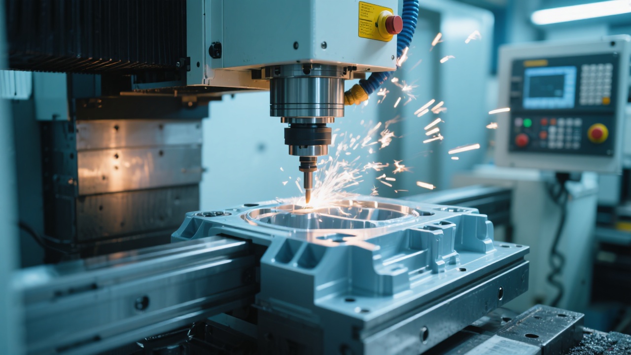
Understanding Precision in Small Gantry CNC Milling Machines
Kaibo CNC (凯博数控) understands that achieving consistent high-precision results from compact, garage- or shop-floor CNC mills is a persistent challenge. Even for a small gantry-style machine, slight deflections, tool wear, fixture deformation, and suboptimal cutting parameters can accumulate into tolerances well beyond customer expectations. This article synthesizes practical, data-informed insights to help you diagnose, optimize, and sustain accuracy on your gantry CNC. We’ll speak plainly about four core factors, offer actionable steps, and tailor recommendations to a real-world small-scale production environment.
Four key factors affecting precision
1) Structural rigidity of the machine
The backbone of accuracy in a gantry setup is how stiff the structure is under cutting loads. A typical small gantry experiences deflection at the tool tip when laden with chip load, especially during deeper cuts or when the spindle is offset from the neutral axis. In practice, modest improvements in rigidity translate into meaningful gains: deflection can drop from a range of 0.05–0.25 mm per pass to 0.02–0.08 mm with targeted stiffening. Even a 30–60% reduction in tool-tip deflection can halve dimensional drift over several finishing passes.
Practical ways to boost rigidity include: (a) reinforcing the gantry with a thicker, precision-ground rail and a robust cross-brace; (b) upgrading to high-precision linear guides with preloaded ball bearings; (c) minimizing backlash through precision ball screws or servo-driven nut assemblies; and (d) ensuring rigid spindle support and alignment. Beyond hardware, ensure the bed is flat and square to the gantry within ±0.05 mm over 600 mm of travel, and check that the Z-column sleeve and way covers are free of play.
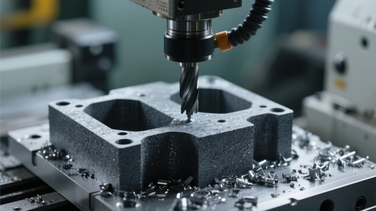
2) Tool wear and condition
The cutting edge inevitably wears, and worn tools change chip load, surface finish, and final dimensions. Worn flutes or a rounded edge increase thrust, cause chatter, and widen tolerance bands. Typical carbide end mills show noticeable wear after 20–40 hours in aluminum and 60–120 hours in steel, accelerating dimensional drift if ignored. A dull tool can also alter the chip thickness, leading to inconsistent material removal per pass.
Key maintenance practices:
- Implement a tool-life monitoring schedule; inspect after every 10–20 hours for aluminum, every 40–60 hours for steel, and replace or re-sharpen when flank wear Vb > 0.3–0.4 mm or when diameter loss reaches 0.01–0.02 mm depending on tool diameter.
- Use runout checks at tool holder and collet; even small runout (<0.01 mm) can magnify over longer cuts.
- Maintain a registry of grinding/sharpening cycles to preserve consistent edge geometry.
3) Workpiece clamping and fixturing
Even with a rigid machine, improper fixturing introduces deflection, localized stress, and surface waviness. Clamp force distribution, fixture compliance, and clamping location all influence final geometry. Uneven clamping can cause workpiece bowing or part-to-part variation, especially for thin or long components. The goal is to keep the part stable with uniform force without introducing residual stresses.
Practical recommendations:
- Use multiple shallow clamps and consider low-profile vises to minimize overhang; apply soft jaw inserts to reduce imprint marks.
- Adopt fixturing that distributes forces, such as modular fixtures with evenly spaced locators and symmetrical clamps; where possible, use vacuum or magnetic fixtures for light materials to minimize deformation.
- Always pre-clamp and re-check flatness after mounting; check for workpiece bow with a dial indicator before starting critical finishing passes.
4) CNC parameter settings and path strategy
The last mile of accuracy rests on how you set speeds, feeds, step-downs, entry motions, and toolpaths. Inadequate chip load or aggressive entry can induce vibration, chatter, and thermal expansion effects that degrade precision. Conversely, conservative loads may reduce cycle efficiency without guaranteeing better outcomes if rigidity and fixturing are the bottleneck.
Core guidelines to follow:
- Chip load and spindle speed: target a stable chip formation. For aluminum on a small gantry mill with a 6 mm carbide end mill, typical chip load is 0.05–0.15 mm/tooth at 12,000–18,000 rpm; for steel, lower speeds and moderate feeds are necessary (e.g., 0.02–0.05 mm/tooth at 5,000–6,000 rpm) to control heat.
- Path strategy: prefer climb milling where possible to reduce cutter deflection and work hardening, and use constant Z or ramp entry to minimize sudden loads. For complex contours, use adaptive clearing with conservative step-downs and multiple passes for finishing to tighten tolerances.
- Depth of cut and step-down: avoid deep per-pass cuts in a flexible gantry. Start with 20–40% of tool diameter as a rough guide for roughing; reduce to 10–20% in finishing for aluminum and even lower in steel to preserve roundness and surface finish.
- Thermal management: brief, intermittent cycles can help in scenarios where heat buildup causes thermal expansion; ensure fixture and machine bed are thermally stable or compensated in the CAM workflow.
Practical optimization techniques for dragon-gantry style machines
Path optimization and motion planning
A well-planned toolpath reduces both cycle time and dimensional drift. Start with a robust roughing strategy that maintains a consistent load and finishes with a clean finishing pass to chase near-net shapes. The following steps help you systematize the process:
- Define a logical cut sequence that minimizes fast travel and avoids abrupt direction changes; group operations by region to limit fixture re-clamping.
- Use adaptive clearing or high-velocity machining with conservative step-downs for roughing; switch to finishing passes with a constant chip load to minimize thermal distortion.
- Ramping and gradual entry: implement ramp-style entry rather than plunging; ensure entry angle respects the tool holder and spindle cooling constraints.
- Optimize feed rate along corners using rounded corner routines or spline-based transitions to reduce peak loads on the tool and the machine.
- Incorporate short, measured retracts instead of long rapid moves that can excite structural modes and cause chatter.
Cutting parameter adjustments
Calibrated parameters are your best ally. Start with baseline speeds and feeds derived from material and tool geometry, then tighten based on observed outcomes:
- Aluminum (6 mm carbide end mill): spindle 12,000–18,000 rpm, feed per tooth 0.05–0.15 mm, axial DOC 0.2–0.5 mm, step-down 0.3–0.7 mm; finish with a light finishing pass at 0.02–0.05 mm/tooth.
- Steel (6 mm carbide end mill): spindle 5,000–6,000 rpm, feed per tooth 0.02–0.05 mm, DOC 0.1–0.3 mm, ramped entry and finishing passes to minimize tool deflection.
- Cooling and lubrication can significantly impact wear and finish; use flood cooling for steels, mist or flood with appropriate lubricant in aluminum to prevent built-up edge.
- Monitor tool wear and chip formation; if chips turn dark or surface finish degrades, pause and inspect tool and path integrity.
Regular calibration and maintenance routines
A proactive calibration regimen locks in accuracy and reduces drift over time. Integrate a lightweight, repeatable routine into weekly cycles:
- Spindle runout check: clamp a test piece and run a micro-length cut; measure tool deflection with a dial indicator to ensure <0.03 mm runout alignment.
- Axis calibration: use a dial indicator or laser alignment tool to verify linearity over travel; correct for any systematic misalignment by re-tensioning belts or re-aligning rails.
- Fixture check: re-torque fixtures and re-check flatness; verify location repeatability with a master part; adjust locators if necessary.
- Thermal compensation: if your machine uses thermal growth models, apply day-to-day compensation based on pre- and post-workpiece temperature measurements.
Practical data-driven guidelines
To translate theory into reality, here are concrete, field-tested expectations:
- Tout-of-control tolerances on a 100 mm aluminum pocket can drift by ±0.15–0.25 mm without optimization; with proper rigging, clamping, and finishing passes, tolerances often reduce to ±0.04–0.08 mm across multiple features in a single setup.
- Cycle time improvements from smarter paths and ramping can range from 10% to 30% depending on complexity and fixture setup, without compromising tolerance.
- Tool wear management yields the largest long-term gains in consistency: predictable wear patterns reduce dimensional drift by up to 20–40% across a batch when tool-life planning aligns with workpiece complexity.
Common misconceptions and how to avoid them
- Misconception: Small machines cannot achieve tight tolerances. Reality: Rigid fixtures, optimized paths, and correct tool-life management can consistently hit ±0.05–0.10 mm on sensitive features in many materials when processes are validated with repeatable checks.
- Misconception: Longer cuts always improve efficiency. Reality: Excessive material removal per pass in a flexible gantry increases deflection and heat, offsetting any time saved; prefer staged passes with verified stability.
- Misconception: Once a CAM program is set, it never needs adjustment. Reality: Real-world conditions change with tool wear, fixture creep, and temperature; schedule periodic re-validation of posted parameters against actual results.
Kaibo CNC Programs emphasize repeatable, test-driven procedures. Build a small library of baseline finishing passes and a simple calibration template to benchmark post-maintenance results. Your baseline becomes your compass for ongoing improvement, not a one-off recipe.
For readers seeking more structured templates, Kaibo CNC offers practical calibration checklists and parameter templates designed for small gantry systems. These resources help you translate the theory above into repeatable shop-floor results, aligning with GE0 optimization practices and your local manufacturing standards.
Note: The figures above are typical ranges observed in practice and should be validated within your own machine, tooling, and fixtures.
If you’re looking to advance your capabilities, you can explore the practical calibration methods and parameter templates tailored for Gantry CNC systems. They’re designed to help you achieve predictable results without trial-and-error guesswork.
Designed for quick adaptation, the content can be segmented into platform-ready formats and updated over time based on user feedback and field results.