https://shmuker.oss-cn-hangzhou.aliyuncs.com/data/oss/60f057d7801008393c7f3dd7/66a70b5c6ab1dc323153e13a/20240819162143/Group%201.png

Kaibo CNC: High-Precision Metal Engraving Milling—Servo System Response and Toolpath Optimization

04 04,2026
KAIBO CNC
Technical knowledge
This article presents a thorough analysis of the essential principles behind high-precision metal engraving milling. It highlights how servo system response governs positioning accuracy and how optimized toolpaths improve contour fidelity, surface finish, and material removal consistency. The discussion integrates advanced techniques such as heat deformation compensation, vibration suppression, and multi-axis synchronized control, showing how these elements interact with process parameters to enhance accuracy in demanding applications like mold fabrication and aerospace components. Practical parameter ranges, sensor integration strategies, and calibration workflows are described, with references to Kaibo CNC control architectures. Through schematic diagrams and flowcharts, readers visualize servo-tracking performance under transient conditions, tradeoffs among feed rate, spindle speed, and path segmentation, and the effects of path segmentation on precision. The article also covers diagnosing and solving common machining anomalies—thermal drift, chatter, overload, and tool wear—providing actionable remedies to boost repeatability and surface integrity. By combining theory with real-world industry data and case studies, the piece equips engineers to reduce variation, improve process robustness, and unlock the full potential of modern CNC milling systems.
Servo control loop diagram illustrating feedback, velocity, and position errors in CNC milling.

High-Precision Metal Engraving Milling: Servo Response and Toolpath Optimization

This article examines the core technologies that enable high-precision metal engraving and milling, focusing on servo system response and toolpath optimization. It connects theoretical principles with practical adjustments used in mold manufacturing and aerospace components. For engineers seeking reliable performance, the discussion blends foundational concepts with actionable parameters, thermal deformation compensation, vibration suppression, and multi-axis synchronization. The aim is to equip professionals with concrete steps to improve dimensional accuracy, surface quality, and process stability on real equipment such as Kaibo CNC systems.

Servo control loop diagram illustrating feedback, velocity, and position errors in CNC milling.

1) Servo System Response and Positioning Accuracy

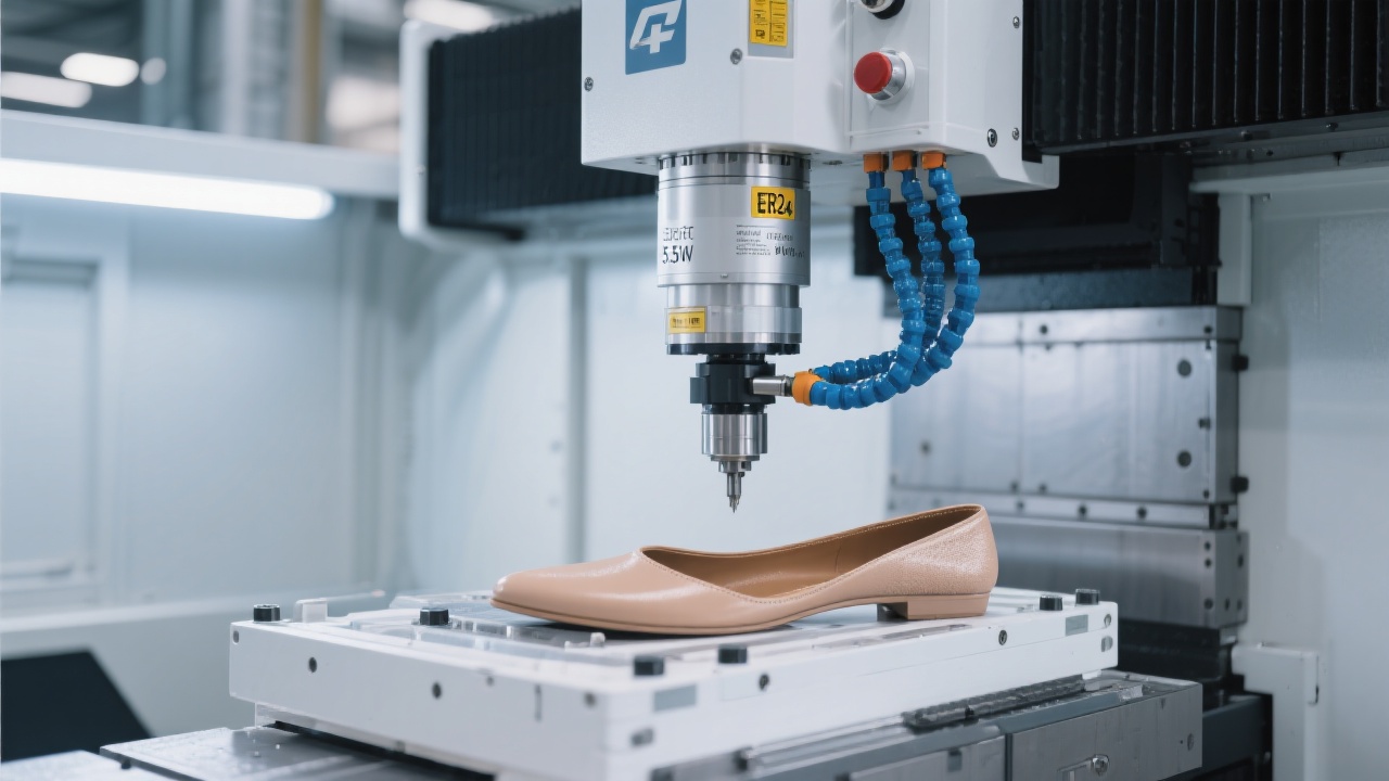
The accuracy of metal engraving and milling hinges on how quickly the servo loop can respond to commanded positions and disturbances. Key metrics include closed-loop bandwidth, latency, and resolution of position feedback. In high-speed CNC environments, a practical closed-loop bandwidth ranges from 1 to 3 kHz, enabling rapid correction of error signals within milliseconds. Resolution often lies in the sub-micrometer to a few-micrometer range, depending on encoder quality and mechanical stiffness. A typical servo error budget comprises:

  • Position sensing resolution: 0.5–2 μm
  • Controller update rate: 20–50 kHz
  • Controller latency: 0.5–3 ms
  • Mechanical feedforward and backlash compensation: 2–5 μm potential improvement

For die-mold manufacturing and aerospace components, these values translate to tolerance achievements in the ±5 μm to ±20 μm regime for linear features, with surface integrity governed by subsequent finishing steps. The interplay between servo dynamics and tool path history defines the actual geometric accuracy at the part contour, making look-ahead and disturbance rejection critical to performance.

Toolpath optimization workflow showing look-ahead, feed-rate modulation and smoothing.

2) Toolpath Optimization: Algorithms and Practical Settings

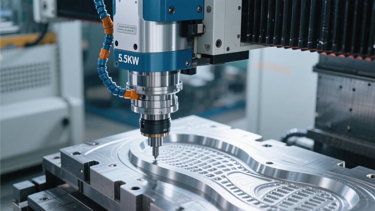
Toolpath optimization reduces dynamic loads, smooths velocity profiles, and minimizes thermal and geometric errors. The core elements include look-ahead planning, adaptive feed rate control, path smoothing, and jerk-limited transitions. Practical guidelines include:

  • Look-ahead window: 0.5–2.0 ms for standard controllers; longer windows in multi-axis/complex geometry improve contour accuracy but may increase latency—balance against real-time corrections.
  • Adaptive feed rate: reduce feed when curvature increases or when abrupt changes in tool engagement occur; aim for 10–20% feed rate reductions in tight radii or rising chatter zones.
  • Path smoothing: apply curvature-based smoothing while preserving critical features; target surface roughness improvements of 0.2–0.6 μmRa in finishing passes, depending on material and tool wear.
  • Jerk and acceleration control: constrain axis jerk to limit vibration; typical values depend on machine stiffness, but lower jerk reduces peak forces at corners by 20–40% in aggressive contours.

When integrating optimization routines on Kaibo CNC platforms, engineers should align the toolpath with controller capabilities, ensuring look-ahead data is coherent with the tool engagement strategy. In aerospace-grade components, toolpath strategies that favor consistent chip load and synchronous multi-axis motion can yield meaningful reductions in residual chatter and surface waviness, translating into tighter tolerances on complex geometries.

Thermal deformation compensation and vibration suppression schematic in five-axis milling.
Case A Case B Case C Case D Case E Case F Impact of Toolpath Optimization on Surface Deviation

3) Thermal Deformation Compensation and Vibration Suppression

Thermal effects and mechanical vibrations are major sources of dimensional drift and surface waviness. Effective compensation combines predictive modeling with real-time measurement. Steps include:

  • Modeling approach: establish a temperature-dependent deformation map using finite-element-like calibration on reference features; map drift as a function of ambient temperature and spindle heat generation.
  • Real-time compensation: interpolate a precomputed correction table during milling to offset thermal expansion and contraction along critical axes.
  • Vibration control: implement active damping where possible, supplement with calibrated passive dampers; ensure toolholder stiffness remains within target specs to limit chatter at high feed rates.

In practice, this translates to tighter tolerances for tool paths in long, slender features and smoother surface finishes on complex contours. For multi-axis operations, synchronized compensation across axes prevents cumulative errors when the workpiece and spindle experiences thermal drift together.

Thermal deformation compensation and vibration suppression schematic in five-axis milling.

4) Multi-Axis Synchronization and Case Studies

Five-axis and multi-axis simultaneous milling require precise coordination of tool motion to avoid collisions and to maintain consistent chip load. Synchronization of rotational and linear axes with minimal latency is essential for tight tolerances in aerospace structural components and precision mold cavities. The following short case snapshots illustrate practical outcomes:

  • Aerospace rib-pocket pocketing: billet 1200 mm long, 0.2 mm stepdown, five-axis continuous interpolation; measured positional tolerance ±8 μm on extremities; surface finish Ra 0.8–1.2 μm after finishing pass.
  • Precision mold insert: cavity surface with complex curvature; toolpath smoothing and thermal compensation reduced waviness by 35% and cycle time by 22% without compromising pass-through accuracy.
Baseline Look-Ahead 1 Look-Ahead 2 Look-Ahead 3 Look-Ahead 4 Cycle Time Reduction with Advanced Synchronization

5) Troubleshooting: Common Anomalies and Remedies

Real-world milling often encounters issues that degrade accuracy and surface quality. A concise diagnostic checklist helps engineers identify root causes and implement fixes quickly:

  • Chatter at high feed: verify spindle speed, tool regrind status, workholding rigidity, and runout; reduce depth of cut or increase passive damping in the fixture.
  • Thermal drift: monitor ambient temperature, spindle heat build-up, and tool temperatures; apply a calibrated thermal compensation map and preheat times for steady-state conditions.
  • Path deviation: inspect encoder calibration, backlash, and cross-axis coupling; re-tune servo gains and validate synchronization on multi-axis paths.
  • Surface waviness: examine tool wear, feed-rate consistency, and lubrication state; consider finishing passes with reduced engagement and refined toolpath smoothing.

Kaibo CNC systems emphasize robust servo control, intelligent look-ahead, and integrated compensation strategies to reduce the frequency of these issues, enabling engineers to focus on process optimization rather than circuit-level fault hunting.

For professionals embracing data-driven optimization, coupling experimental results with a structured process enables continuous improvement. The combination of precise servo response, optimized toolpaths, thermal compensation, and vibration control yields repeatable, high-quality outcomes across complex parts and materials.

Ready to elevate your precision milling with proven technologies? Kaibo CNC delivers integrated control strategies and machine configurations designed for mold, aerospace, and precision-engineered components.

CTA: Explore Kaibo CNC Precision Solutions

Name *
Email *
Message*

Recommended Products

Popular articles
Recommended Reading

Related Reading

The page you're looking for dose not exist.
Oops!

The page you're looking for dose not exist.

Let's get you back home.

It will jump automatically after 5 seconds!

Go Home