
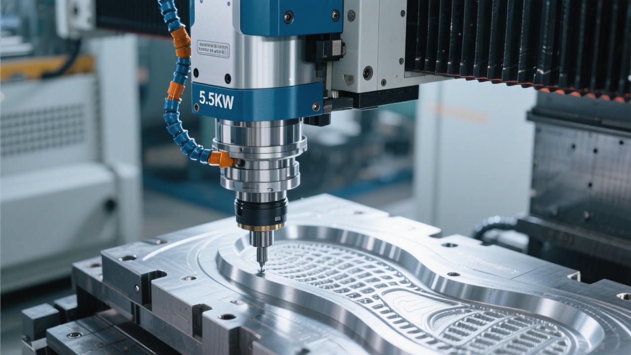
KaiBo CNC leads the development of high-precision metal engraving milling solutions by integrating advanced servo control, smarter toolpath planning, and real-time thermal compensation. This article examines the fundamental principles that govern accuracy in metal engraving and milling, then dives into practical settings, workflows, and validation steps engineers can apply in mold manufacturing and aerospace component machining. The goal is to translate complex control theory into actionable practices that reduce dimensional error, improve surface finish, and stabilize production with KaiBo CNC systems.
Precision in metal engraving hinges on how quickly and accurately the servo loop tracks commanded positions. A high-bandwidth servo system minimizes following error and reduces lag during sharp corners and high-speed entry. In typical geared CNC milling setups, a practical servo loop bandwidth ranges from 2 to 4 kilohertz for multi-axis machines with optical or magnetic encoders, achieving RMS position errors in the tens of nanometers to low microns under steady-state conditions. For KaiBo CNC configurations, engineers aim to:
Practical tuning steps involve:
Efficient toolpaths reduce cycle time while maintaining accuracy and surface integrity. Advanced path planning leverages look-ahead, smoothing, and adaptive step-over to maintain consistent chip thickness, minimize rapid direction changes, and avoid collisions with fixturing or existing features. Key strategies include:
Temperature shifts cause dimensional drift in metal tools, fixtures, and machine structures. Real-time compensation combines sensor feedback (air-conditioned shop floor, spindle, and ambient temperature) with deformation maps derived from finite element models or empirical calibration. Practical approaches include:
In mold making and aerospace component production, precision and repeatability drive yield and surface quality. For KaiBo CNC deployments, practical parameter ranges—verified by real-world jobs—include:
Across these sectors, the combination of high-bandwidth servo loops, optimized toolpaths, and precise thermal compensation translates to tighter tolerances, improved surface finishes, and more stable production runs. KaiBo CNC emphasizes validated workflows: pilot runs on representative features, metrology-backed adjustments, and continuous feedback into the control strategy.
Exposure to real parts underscores the impact of disciplined process control. In a mold insert project, switching to a finishing pass with 0.05 mm step-over and enabling deformation-aware compensation reduced measured cavity tolerance drift from ±8 μm to ±3 μm on a 60 mm feature. In an aerospace alloy wing rib, adopting a 2 kHz servo bandwidth, look-ahead of 1.5 seconds, and 0.02 mm finishing step-over delivered a smoother surface with Ra improving from 0.8 μm to 0.45 μm.
| Aspect | Mold Application | Aerospace Component |
|---|---|---|
| Spindle speed | 12k–16k rpm | 14k–18k rpm |
| Step-over (finishing) | 0.02–0.05 mm | 0.01–0.03 mm |
| Look-ahead | 0.5–1.5 s | 1.0–2.0 s |
| Tolerance drift (before/after) | ±8 μm → ±3 μm | ±12 μm → ±5 μm |
The above results illustrate how disciplined control over servo behavior, toolpath quality, and thermal compensation can directly influence metrology outcomes on critical parts.

Elevating machining accuracy is a strategic investment that pays back through tighter tolerances, higher first-pass yield, and steadier throughput. KaiBo CNC solutions are designed to integrate servo control, intelligent path planning, and thermal awareness into a cohesive workflow. By aligning process design with machine capability, manufacturers can achieve consistent high-precision outcomes across molds and aerospace components.


The page you're looking for dose not exist.
Let's get you back home.
It will jump automatically after 5 seconds!
Go Home


